|
 |
|
|
|
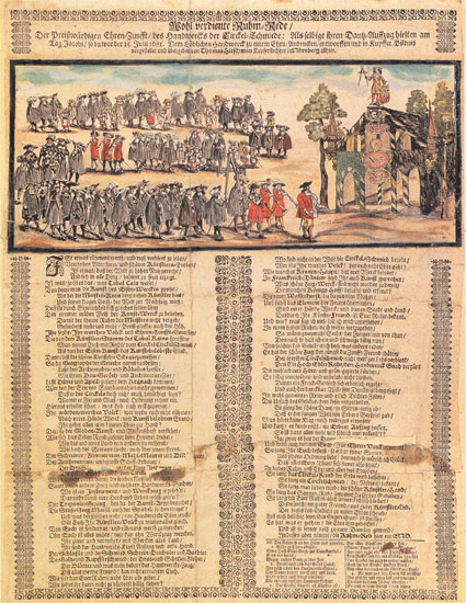
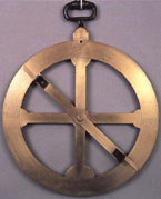
Illustration of the nautical astrolabe, presented by Simão de Oliveira in Arte de navegar, Lisbon, 1606
|
|
|
|
 |
|
|
|
Circular dividing engine invented by Jesse Ramsden. Drawing included in his work Description of an engine for dividing mathematical instruments, London, 1787.
|
|
|
|
 |
|
|
|
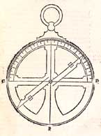
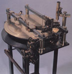
Circular dividing engine, manufactured by the company Froment, Paris, 1855. Instituto Superior Técnico, Lisbon.
|
|
|
|
 |
|
|
|
The nautical astrolabe Coimbra, with a diagonal scale. Despite its name, it was not used on board due to its size (diameter 508 mm, weight 10170 g). Astronomical Observatory of the Universidade de Coimbra.
|
|
|
|
Astronomical navigation began in the fifteenth century, when Portuguese navigators, on moving away from the coastline, had to resort to instruments that measured altitude in order to determine the position of the ship. For this they used quadrants and nautical astrolabes which, naturally, had to be well divided so as to ensure the accuracy of their calculations.
This requirement was such that in the subsequent century, the Regimento do Cosmógrafo-mór, promulgated in 1592, established that artisans of sea-charts and manufacturers of nautical instruments had to be subjected to examination. They had to be checked by the Principal cosmographer who had to sign them, certifying their quality. The Regimento went so far as to impose fines on manufacturers who did not subject themselves to examination and on approved artisans who did not submit their works to examination.
The division of the scale of a quadrant or of an astrolabe was no easy task. Simão de Oliveira, in his Arte de Navegar, published in 1606, tells us: “Now that the astrolabe has been described, it must be divided in the following manner: each upper quadrant shall be divided into 3 equal parts, each of which in turn shall be divided into a further 3 parts, making a total of 9. These 9 parts shall be further divided in half, making a total of 18 parts, which shall each be divided into 5 equal parts. Each of the upper quadrants shall therefore be divided into 90 equal parts. A rule shall be added to the centre of the circle, which shall be used to trace small lines, with those spaced at 10 degree intervals being traced at both intervals and those spaced at 5 degree intervals being traced at one interval and part of the other and those spaced at a 1 degree interval being traced at only one interval, one degree being white and the other black, on which the number shall be written at 10 degree intervals, with the ten starting on point A and finishing on C and D where the 90 will be placed.
Now that the astrolabe has been described and drawn on paper, we shall move on to the brass astrolabe, marking the circles and lines at the same distance, division and number as on paper, describing the circles with a steel-pointed compass and the lines with one of its points, so that the brass is cut marking the degrees with small lines, just as on paper one was drawn in white and the other in black”.
In sum: the artist had to make the drawing on paper first and then transfer it to the quadrant or astrolabe, committing several errors in this process, which started with the fact that there were no geometrical methods of dividing the quadrant of a circle and which ended with the lack of accuracy in the engraving.
|
 |
|
|
|
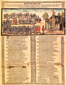
(click on the picture above to see an enlarged version)
In Nuremberg, where in the past the production of scientific instruments was important, scale dividing artificers, who were very prestigious, made an annual procession, in this case held on 25 July 1681. Drawing by Thomas Hirschman. Staadtgeschichtliches Museum, Nuremberg.
|
|
|
In the eighteenth century, the process of dividing the scales had been improved. In 1767, John Bird (1709-1776) published a work called "Method of dividing astronomical instruments”, where he presents some innovative methods, which he considered more appropriate. He recommended that the work be done in the morning, under constant temperature conditions, choosing specific seasons of the year to do so, such as spring and autumn, for example.
To obviate the difficulty in dividing the quadrant, due to there being no geometrical method to do so, the inventor George Graham (1673-1751), suggested dividing it into 96 parts, i.e. first into 3 parts and then bisecting it repeatedly until this number was reached. A conversion table would easily provide the measurement of the angle measured in degrees. This solution, put forward by the scientist João Jacinto de Magalhães, was never successful, however.
One method of avoiding the troublesome problem of dividing the circular scales was to use instruments which were designed to measure angles and which used rectilinear scales, as was the case with the cross staff, which was also used by Portuguese navigators since the beginning of the sixteenth century.
In the face of all of these difficulties, it became crucial and urgent to find a mechanical solution to resolve this pressing problem. After the unsuccessful attempts of others, between 1768 and 1773, Jesse Ramsden (1731-1800) designed and developed the circular dividing engine (Fig. 2), which became truly famous. The machine was later presented in the work “Description of an engine for dividing mathematical instruments”, published in London in the year 1787, making Ramsden one of the most illustrious manufacturers of instruments of his time.
The great innovation of this artist, who had a workshop in London, was to include in his machine a wheel with 2160 teeth connected to a screw jack, which, for each rotation, permitted a division of 10 minutes of arc. As this screw jack was activated by another wheel divided into 60 parts, the machine reached 10 seconds, much more than was required of a nautical instrument, but which was extremely useful in the manufacturing of material to be used for astronomical observations on land. Once the appropriate division had been chosen, the circular edge of the instrument was scratched using a stiletto, achieving in a short space of time something that took days to achieve and which in terms of precision had no comparison.
If Ramsden had been born in another country, he might have been the only one to benefit from his invention for quite some time. In England, however, the Board of Longitude, which had been created to find a practical solution to determine longitude at sea, awarded Ramsden 300 sterling pounds as a prize for his invention. He received a further 315 pounds on the condition that he publish a project information memorandum and place himself at the disposal of ten of his fellow artificers chosen by the Board in order to teach them how to manufacture similar machines and how to use them.
This intelligent division was one of the main reasons for the amazing technological development and consolidation of the prestige already achieved by English manufacturers, not only of nautical instruments but also of other commonly called mathematical instruments.
Moreover, Jesse Ramsden was made a member of the Royal Society. This fact alone was a measure of great incentive for, as was known, other academies of a similar nature did not open their membership up to a mere artificer. In fact, another master artificer, Peter Dollond (1730-1820) also became a member of this prestigious institution for having corrected the chromatic aberrations of the lens employed in instruments used for astronomical observations. Ramsden benefited from the patent of this invention when, in 1765, he married Dollond’s sister.
We do not know who the first Portuguese artificers to use this type of circular dividing engine were. The oldest example of this machine in Portugal is believed to be the one found in the Museum of the Instituto Superior Técnico. It was fabricated in France in the year 1855 by the firm Froment.
Another problem related to measuring instruments consisted of reading the fractions of the smallest division of a scale, which was almost certainly done by estimation, meaning that it was not a very accurate operation. Moreover, it depended on the personal evaluation of the observer.
 |
|
|
|
|
Drawing of a transversal or diagonal scale, which shows how the width of the smallest division of a scale can be expanded.
|
|
|
|
Levi ben Gerson (1288-1344) was a Jew who lived in the south of France and who left a manuscript in Hebrew, which Petrus de Alexandria translated into Latin in 1342, at the request of Pope Clemente VI. In this manuscript, Levi proposed the use of a transversal scale, also called diagonal scale (Fig. 4). It is vital, nevertheless, to mention that in the past the priority of this method was awarded to Thomas Digges (1546-1593), who in 1576 presented it in his work "A perfil description of the celestial orbes”. We do not know, however, if Digges knew of Levi’s work as in the past it was common practice to refer or use the inventions of others without indicating its true authors.
In practice, this method consists of ingeniously expanding the width of the smallest part of the scale using diagonals between the extreme values, yet respecting parallel scales. In this way, it becomes possible to obtain the space necessary in order to mark the subdivisions, both on the rectilinear and circular scales.
There are known to be instruments which have a transversal scale, as is the case of the Coimbra, a nautical astrolabe, possibly dating back to the end of the seventeenth century, which can be found in the Astronomical Observatory of the University of Coimbra. This type of scale was used in the first octants, fabricated in the middle of the eighteenth century.
|
|